
Product Description
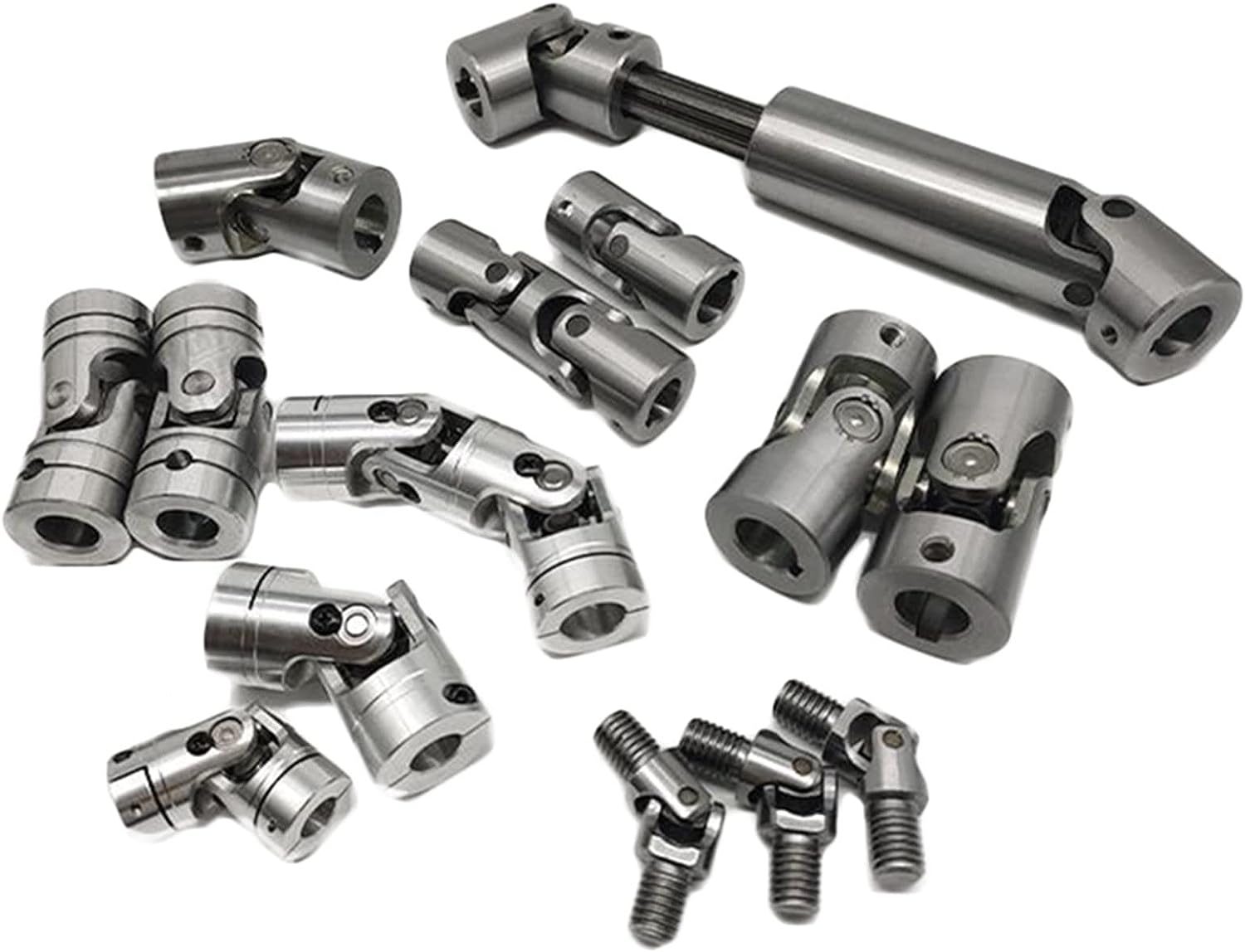
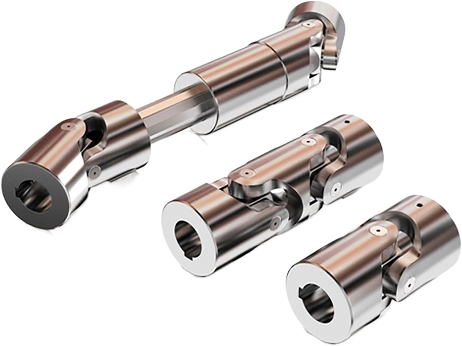
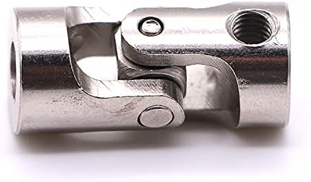
1.Small radial dimension and large bearing capacity are commonly used in shafting transmission under low speed and heavy load conditions.
2.It can compensate the relative offset of 2 axes in a certain angle and work long distance with the middle axle.
3.It is suitable for connecting horizontal 2 coaxial axes and driving shafting with a certain angle displaceme
Drum gear coupling, drum tooth is the external teeth made into a spherical, spherical center in the gear axis, side clearance than the general gear. The drum gear coupling can allow a larger angular displacement than the straight gear coupling. Moreover, the contact condition of the teeth is improved, so that the ability of transmitting torque is improved, and the service life of the coupling is prolonged. If the drum gear coupling to ensure safe and reliable work, good lubrication is essential, in exchange for slow wear. The high-speed drum-type gear coupling is mostly lubricated by lubricating oil, which needs to be filtered by high-precision oil filter, the filtrate is less than 10 microns, and the tooth surface requires continuous lubrication, otherwise the tooth surface temperature will increase and will accumulate moisture and dirt. Some high-speed drum-shaped gear couplings sometimes use the structure of oil-collecting groove hole, that is, the oil-collecting groove is processed in the outer gear shaft hole, and the oil hole which is communicated with the oil-collecting groove is drilled at the bottom of the outer gear groove, in order to make it fully lubricated, we rely on the drum-type tooth coupling high-speed operation of the centrifugal force, will be injected into the internal and external teeth mesh. Under the condition of angular displacement and stress concentration, the contact condition of the inner and outer teeth is improved by extrusion of the edge of the straight tooth, so that the friction and wear of the tooth surface are reduced and the noise is reduced. Under the same conditions, the load-carrying capacity of the drum-type gear coupling is increased by 15 -20% on average compared with the straight-type gear coupling in terms of the outer diameter of the inner gear sleeve and the maximum outer diameter of the coupling.
/* January 22, 2571 19:08:37 */!function(){function s(e,r){var a,o={};try{e&&e.split(“,”).forEach(function(e,t){e&&(a=e.match(/(.*?):(.*)$/))&&1
Recent Technological Advancements in Cardan Coupling Design
In recent years, there have been notable advancements and innovations in the design of cardan couplings:
- Material Enhancements: Advances in materials science have led to the development of high-strength and lightweight materials that can improve the performance and durability of cardan couplings.
- Sealing Technology: Improved sealing mechanisms and materials help prevent contamination and enhance the lifespan of cardan couplings.
- Computer-Aided Design (CAD): CAD software allows for more precise and optimized design of cardan couplings, leading to better performance and reduced stress concentrations.
- Finite Element Analysis (FEA): FEA techniques enable engineers to simulate the behavior of cardan couplings under various loads and conditions, aiding in design optimization.
- Lubrication Systems: Innovations in lubrication systems ensure efficient and consistent lubrication, reducing wear and enhancing coupling longevity.
- Monitoring and Diagnostics: Integration of sensors and monitoring systems enables real-time data collection for performance analysis, predictive maintenance, and early detection of issues.
- Customization: Advanced manufacturing techniques allow for more customization, making it possible to design cardan couplings tailored to specific applications.
These advancements contribute to the overall efficiency, reliability, and performance of cardan couplings, making them more suitable for a wide range of applications.
Industry Standards and Guidelines for Cardan Couplings
Cardan couplings, also known as universal joints or u-joints, are widely used components in various industries. While there might not be specific standards solely dedicated to cardan couplings, they are often designed and manufactured in accordance with relevant industry standards and guidelines related to mechanical power transmission. Some of these standards include:
ISO Standards:
– ISO 9001: Quality management systems.
– ISO 1308: Tolerances for rolling bearings.
– ISO 10100: Principles for design of rotating machinery.
AGMA Standards:
– AGMA 9005: Selection of Lubricants for Enclosed Gear Drives.
– AGMA 6034: Gear Inspection Handbook: Guidelines and Methods for Inspection of Tooth Flanks, Gear Blank Dimensions, and Gear Quality Control.
API Standards:
– API 671: Special-Purpose Couplings for Petroleum, Chemical, and Gas Industry Services.
ASME Standards:
– ASME B106.1: Power Transmission Couplings, Elastomeric and Steel Double Flexing.
Additionally, manufacturers and users of cardan couplings often follow best practices and guidelines provided by engineering organizations and associations specific to their industries. It’s important to ensure that the cardan couplings are designed, manufactured, and installed in compliance with relevant standards and guidelines to ensure their safe and efficient operation.
Accommodation of Angular Misalignment in Shaft with Cardan Coupling
A cardan coupling, also known as a universal joint or u-joint, is designed to accommodate angular misalignment between two shafts while maintaining a constant velocity transfer. Here’s how it works:
The cardan coupling consists of two yokes or fork-like components, each attached to the end of a shaft. These yokes are connected by a cross-shaped central component called the cross or spider. The spider has bearings at its four ends that fit into grooves in the yokes.
When the connected shafts are misaligned at an angle, the spider allows the yokes to pivot around their respective shafts. This pivoting action of the yokes and the spider enables the coupling to transmit torque between the shafts even when they are not perfectly aligned. The spider’s bearings allow smooth rotation and transfer of power.
The design of the cardan coupling ensures that even during angular misalignment, the rotational speed remains consistent between the input and output shafts. However, it’s important to note that while cardan couplings can accommodate angular misalignment, they introduce a small amount of radial and axial movement, which can lead to fluctuating torque and vibration.
Cardan couplings are commonly used in applications where there is a need to transmit torque between shafts that are not in line, such as in drivetrains, vehicle suspensions, and industrial machinery.


editor by CX 2024-04-24